OpenIMU300RI Evaluation Kit Setup
OpenIMU300RI Evaluation Kit
- To set up OpenIMU300RI evaluation kit you’ll need to perform next steps:
- Install PC tools.
- Unpack OpenIMU300RI evaluation kit.
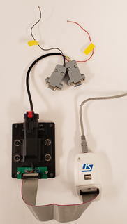
- Connect provided cable to OpenIMU300RI evaluation unit (see notes below).
- Connect cable connector marked “RS232” to the PC serial port or to UCB-to-Serial adapter.
- Connect cable connector marked “CAN” to the CAN bus or to the CAN traffic monitoring unit (like Vestor or Komodo or other).
- Connect ST-Link debugger to the PC via USB cable. Make sure that ST-Link device appeared in “Device Manager”.
- Connect 20-pin connector on OpenIMU300RI evaluation unit to ST-Link debugger using provided 20-pin flat cable.
- Connect RED (+) and BLACK (GND) wires to external power supply (5 - 32V, 0.1A)
- Turn ON power supply.
Now you are ready to debug and test your application.
- The following activities are addressed in the “Development Tools” section:
- Download App with JTAG
- Debugging with PlatformIO Debugger and JTAG Debug Adapter
- Graphing & Logging IMU Data using the Acienna Navigation Studio
Note
The RS232/CAN/Power cable shown in the image is similar to the cable that will be supplied with the kit. It is for information only.
Note
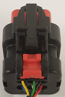
The following directions are applicable for connecting cable to OpenIMU300RI evaluation unit:
- Align the keys on the unit and the cable connector.
- Push the 6-pin cable connector into the unit connector until lock clicks.
- If an extra lock required - push the red latch under the black latch. This prevents the disengagement button from being depressed.
Note
The following directions are applicable for disconnecting cable from OpenIMU300RI evaluation unit:
- If engaged, pull the red latch away from the connector toward the cable.
- Push down on the black disengagement button in the middle of the connector.
- Pull the cable connector away from the unit.
Next table provide connectors pin assignments in provided cable
Signal Name GND 3 5 Black VIN 6 Red RS232 TX 5 2 RS232 RX 4 3 CAN H 1 7 CAN L 2 2
OpenIMU300RI Connector