GPS/INS App
The INS APP supports all of the features and operating modes of the VG/AHRS APP, and it includes additional capability of interfacing with an external GPS receiver and associated software running on the processor, for the computation of navigation information as well as orientation information. The APP name, GPS/INS APP, stands for Inertial Navigation System, and it is indicative of the navigation reference functionality that APP provides by outputting inertially-aided navigation information (Latitude, Longitude, and Altitude), inertially-aided 3D velocity information, as well as heading, roll, and pitch measurements, in addition to digital IMU data.
The processor performs time-triggered trajectory propagation at 100Hz and will synchronize the sensor sampling with the GPS UTC (Universal Coordinated Time) second boundary when available.
As with the AHRS/VG APP, the algorithm has two major phases of operation. Immediately after power-up, the INS APP uses the accelerometers to compute the initial roll and pitch angles. During the first 60 seconds of startup, the INS APP should remain approximately motionless in order to properly initialize the rate sensor bias. The initialization phase lasts approximately 60 seconds, and the initialization phase can be monitored in the operation mode transmitted by default in each measurement packet.
After initialization phase, the OpenIMU continuously maintains the digital IMU data; the dynamic roll, pitch, and heading data; as well as the navigation data. The body frame sensed angular rate is first integrated to orientation at a fixed N times per second. For improved accuracy and to avoid singularities when dealing with the cosine rotation matrix, a quaternion formulation is used in the algorithm to provide attitude propagation. Using the attitude, the body frame accelerometer signals are rotated into the NED frame and integrated to velocity. And then, NED velocity is integrated to get position. At this point, the data is blended with GPS position and velocity data in the EKF, and output as a complete navigation solution.
The INS APP blends GPS derived heading and accelerometer measurements into the EKF update depending on the health and status of the associated sensors. If the GPS link is lost or poor, the Kalman Filter solution stops tracking accelerometer bias, but the algorithm continues to apply gyro bias correction and provides stabilized angle outputs. The EKF tracking states are reduced to angles and gyro bias only. The accelerometers will continue to integrate velocity, however, accelerometer noise, bias, and attitude error will cause the velocity estimates to start drifting within a few seconds. The attitude tracking performance will degrade, the heading will freely drift, and the filter will revert to the VG only EKF formulation. The UTC packet synchronization will drift due to internal clock drift.
Quick Start
In this section, we explain how to get the INS app running with an external GPS receiver that outputs NMEA GGA, VTG and RMC messages. The default baud rate for UART is 115200. Although NMEA is not recommended in our INS app due to lack of some required information of the algorithm, it is chosen here because its popularity and simplicity. Our GPS driver supports NMEA message decoding, so you don’t need to write a single line of code.
It is assumed that you are using our OpenIMU300ZI EVK.
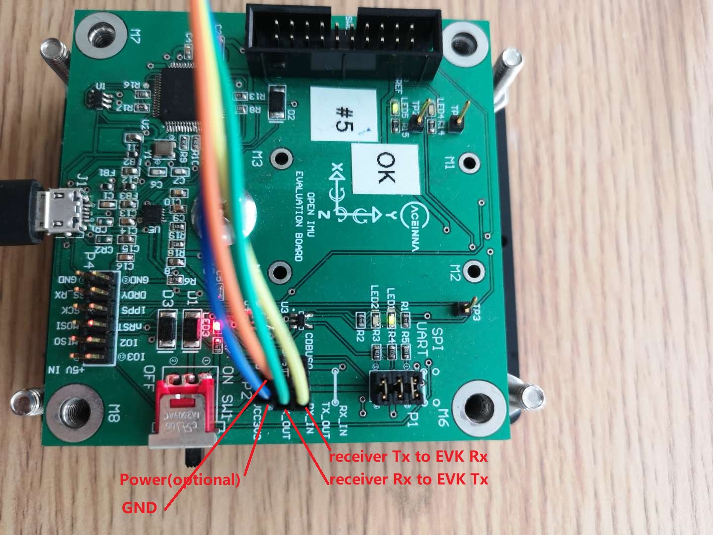
Connect the GPS receiver to the EVK
In the following picture, the onboard 3.3V and GND are used to power the GPS receiver. You can also choose your own power supply.
Burn the INS App into The Unit
The unit has a built-in IMU app. The INS app need loaded by yourself. There are two recommended ways to do that.
Using the Python Driver
This is for people who only want to use the precompiled bin file.
The Python Driver loads the INS app by the built-in bootloader of the OpenIMU300ZI unit. Please follow steps below.
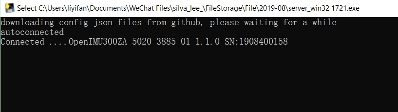
- Connect the unit to the Python Driver.
Please refer to Python Interface. If the unit is successfully connected, you will see information like this.
- Visist the App page of our Developer Site.
You can get access to all available apps in our Developer Site. The OpenIMU300ZI INS app is the one you need.
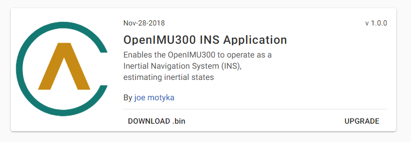
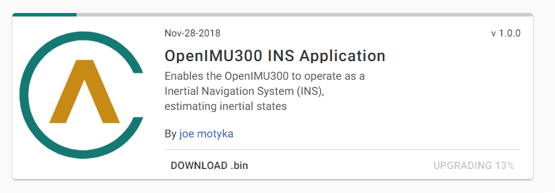
- Burn the INS app.
Click “UPGRADE” and wait for it to complete.
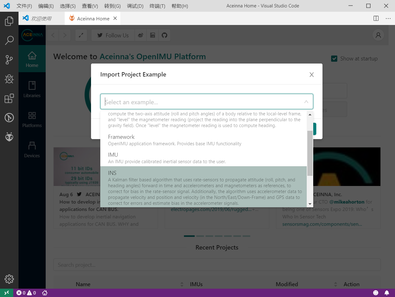
Using Aceinna Extension in VS Code
If you want to modify our open-source code, you may want to try this way.
Please first refer to PC Tools Installation to install required tools and then to Aceinna Extension for basic usage of the extention. After importing the project of the INS app, you can modify the code, compile the project and upload the bin file to the unit via ST-Link.
Get and Visualize the Output
- Connect the unit to the Python Driver.
- Visit our Developer Site.
You can see the detailed information about the unit.
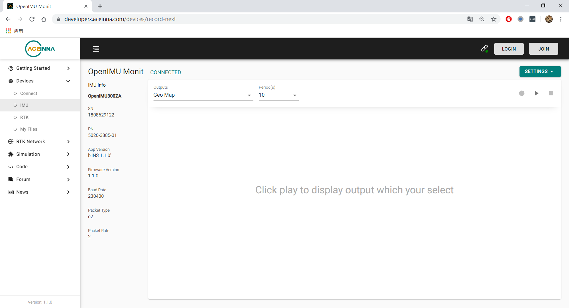
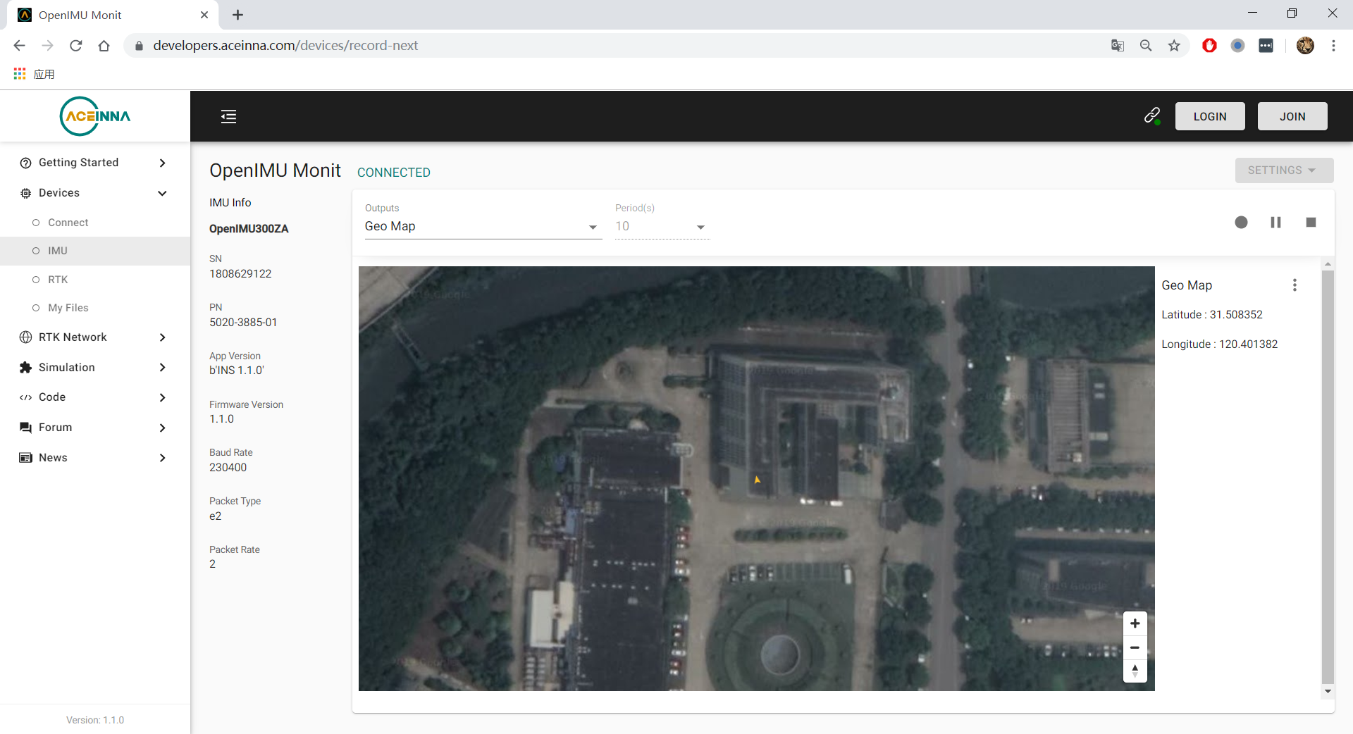
Choose “Geo Map” as output, and click the play button, and you can see the live position on the map.
How to Add Support of a New GPS Receiver Protocal
Currently we support NMEA, uBlox Nav-PVT and NovaTel Bestpos/Bestvel. If your receiver protocal is not in the list, it is easy for you to add code to decode a new protocol. Let’s take uBlox nav-pvt for example to explain how to do this.
define the name (UBLOX_BINARY) of the protocol in GlobalConstas.h.
// Choices for GPS protocol type
typedef enum{
    AUTODETECT              = -1,
    UBLOX_BINARY            =  0,
    NOVATEL_BINARY          =  1,
    NOVATEL_ASCII           =  2,
    NMEA_TEXT               =  3,
    DEFAULT_SEARCH_PROTOCOL =  NMEA_TEXT, // 3
    SIRF_BINARY             =  4,
    INIT_SEARCH_PROTOCOL    =  SIRF_BINARY, ///< 4 max value, goes through each until we hit AUTODETECT
    UNKNOWN                 = 0xFF
} enumGPSProtocol;
2. In driverGPSAllEntrance.c, add this new protocol in SetGpsProtocol(). After this, the new protocal can be set in Aceinna Navigation Studio Web GUI.
BOOL  SetGpsProtocol(int protocol, int fApply)
{
    switch(protocol)
    {
        case NMEA_TEXT:
        case NOVATEL_BINARY:
        case UBLOX_BINARY:
            break;
        default:
            return FALSE;
    }
    if(fApply)
    {
        gGpsDataPtr->GPSProtocol = protocol;
    }

    return TRUE;
}
In driverGPS.c, call the routine to decode this protocol.
switch(GPSData->GPSProtocol){
    case NMEA_TEXT:
        parseNMEAMessage(tmp, gpsMsg, GPSData);
        break;
    case NOVATEL_BINARY:
        parseNovotelBinaryMessage(tmp, gpsMsg, GPSData);
        break;
    case UBLOX_BINARY:
        parseUbloBinaryMessage(tmp, gpsMsg, GPSData);
        break;
    default:
        break;
        }
}
4. Implement the decoding routine (parseUbloBinaryMessage()) in a proper file. For this example, it is implemented processUbloxGPS.c.
The Definition of The Deaulft Output Packet of The INS App
In the section Get and Visualize the Output, we can get INS app output data via the Python driver. The Python driver receives output from the unit, deocde the output packts and then feed decoded results to the Web GUI. If you want to decode the output by yourself, you need to know the structure of the output packet, which is detailed in OpenIMU UART Messaging. The default INS app output packet type is “e2”, and it is defined in the following two tables.
(‘e2’ = 0x6532) Preamble Packet Type Length Payload Termination 0x5555 0x6532 123 <CRC (U2)> Payload:
Byte Offset Name Format Notes 0 U4 4 D 12 Roll F4 16 Pitch F4 20 Yaw F4 24 X acceleration F4 28 Y acceleration F4 32 Z acceleration F4 36 X acceleration bias F4 40 Y acceleration bias F4 44 Z acceleration bias F4 48 X gyro F4 52 Y gyro F4 56 Z gyro F4 60 X gyro bias F4 64 Y gyro bias F4 68 Z gyro bias F4 72 North velocity F4 76 East velocity F4 80 Downward velocity F4 84 X magnetometer F4 88 Y magnetometer F4 92 Z magnetometer F4 96 Latitude D 104 Longitude D 112 Altitude D 120 Operation mode [1] U1 LSB First 121 Linear accel switch [2] U1 LSB First 122 Turn switch [3] U1 LSB First
| [1] | Operation mode of the algorithm. 0 for waiting for the system to stabilize, 1 for initializing attitude, 2 and 3 for VG/AHRS mode, and 4 for INS mode. Please refer to the source code for details. |
| [2] | 0 if linear acceleration is detected, 1 if no linear acceleration. Please refer to the source code for details. |
| [3] | Indicate if the filtered yaw rate exceeds the turn switch threshold. 1 yes, 0 no. Please refer to the source code for details. |
Synchronization to One PPS GPS Signal
The OpenIMU300 has the ability to synchronize a One PPS signal provided by the GPS receiver. The first step in the process is to connect the signal to the correct input pin on the OpenIMU300. In this case, Pin 2 serves as the input as described in Connector Pinout.
See synchronization to external clock signals for more information on how to use the 1 PPS synchronization signal.
About the GNSS/INS Fusion Algorithm
In the INS app, an 16-state extended Kalman filter is implemented to process measurements from a GPS receiver and an IMU unit. If you want to know more details about the algorithm, please refer to EKF Algorithm.
Note
If you have any question, please search or post a new topic on Aceinna Forum.