Connector Pinout - Including GPS Sensor Interface
The OpenIMU300ZI main connector is a SAMTEC FTM-110-02-F-DV-P defined below. The mating connector that pairs with the main connector is the SAMTEC CLM-110-02.
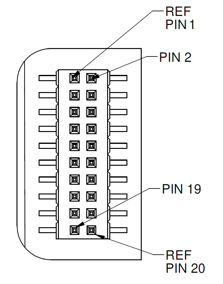
OpenIMU300ZI Interface Connector
J2 is 20-pin connector and it used for connecting the OpenIMU300ZI unit into Open IMU evaluation board. The connector pin definitions are defined in the table below. The GPS-related signals are noted.
Interface Connector Pin Definitions
Pin Main Function Alternative Function 1 GPIO ( IO3 ) Output by default 2 GPS 1PPS Input 3 4 5 6 7 8 External Reset (NRST)) 9 GPIO ( IO2 ) 10 Power VIN (3-5 VDC) Power VIN (3-5 VDC) 11 Power VIN (3-5 VDC) Power VIN (3-5 VDC) 12 Power VIN (3-5 VDC) Power VIN (3-5 VDC) 13 Power GND Power GND 14 Power GND Power GND 15 Power GND Power GND 16 SWDIO (SWD debug interface) 17 18 SWCLK (SWD debug interface) 19 20 Reference voltage for SWD debug interface
Power Input and Power Input Ground
Power is applied to the OpenIMU300ZI on pins 10 through 15. Pins 13-15 are ground; Pins 10-12 accepts 3 to 5 VDC unregulated input. Note that these are redundant power ground input pairs.
Note
Do not reverse the power leads or damage may occur. Do not add greater than 5.5 volts on the power pins or damage may occur. This system has no reverse voltage or over-voltage protection.
Note
Serial channel functions can be arbitrary assigned in the FW. Default assignments are:
In some application examples (INS, VG_AHRS) in file main.c performed reassignment of serial channels to different functions.
Note
Pin 7 needs to be grounded (LOW) upon unit startup to force unit into UART interface mode. To force unit into SPI mode this pin needs to be either unconnected or connected to the input or external device (can be externally pulled UP via 10K resistor).
In SPI mode only serial channel 2 available and can be used for communication with GPS or as DEBUG channel.