OpenIMU300RI Eval Kit
The OpenIMU300RI evaluation kit includes:
- A robust and easy-to-use test fixture.
- An OpenIMU300RI IMU module attached to the test fixture with JTAG (SWD) 20-pin connector.
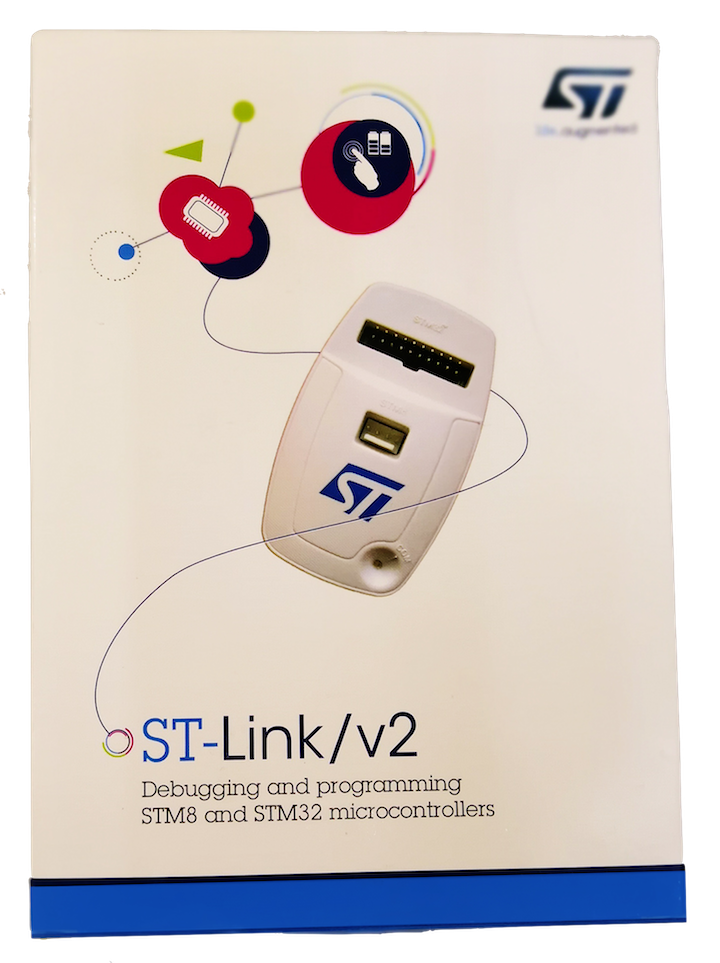
- An ST-LINK J-TAG debugger, a debugger cable, and a USB cable.
- A multiple-connector cable for RS232/CAN/Power connection.

OpenIMU300RI Evaluation Kit Introduction
The OpenIMU evaluation kit is a hardware platform used to evaluate the OpenIMU300RI inertial navigation system and develop various applications based on this platform. It is supported by the Aceinna Navigation Studio, which provides easy access to the features of the OpenIMU300RI and explains how to integrate the device in a custom design. The Components section below provides the contents of the kit.
Note
An external DC power supply is required. The power supply must be able to provide 400mA at 4.9VDC to 32VDC.
The cable shown in the Evaluation Kit figure may look different than the cable that will be provided with the Evaluation Kit
|

|
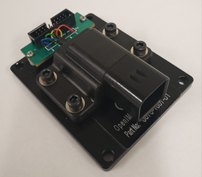
OpenIMU300RI Evaluation Unit
installed on test fixture with JTAG connector
|
OpenIMU300RI Evaluation Kit
|
OpenIMU300RI Evaluation Kit components
OpenIMU300RI unit
OpenIMU300RI is 9 DOF (degrees of freedom) fully calibrated inertial unit. It is used as the base for development custom inertial navigation applications.OpenIMU300RI Evaluation Kit fixture and JTAG header board
The OpenIMU300RI unit with JTAG header board are mounted on the text fixture. The JTAG header provides means to debug/upload applications on evaluation unit.ST-Link debugger
The ST-Link debugger is a standard JTAG SWD debugger provided by STMicroelectronics company. It is used for in-system debugging/uploading of applications via SWD interface.OpenIMU300RI Breakout Cable
An included cable provides means of connecting unit to PC via RS232 interface, connecting unit to the CAN bus and powering up unit.
Next table provides connectors pin assignments in supplied cable
Signal Name GND 3 5 Black VIN 6 Red RS232 TX 5 2 RS232 RX 4 3 CAN H 1 7 CAN L 2 2
OpenIMU300RI Evaluation Kit Setup
To set up OpenIMU300RI evaluation kit you’ll need to perform next steps:
- Install PC tools.
- Unpack OpenIMU300RI evaluation kit.
- Connect provided cable to OpenIMU300RI evaluation unit (see notes below).
- Connect cable connector marked “RS232” to the PC serial port or to UCB-to-Serial adapter.
- Connect cable connector marked “CAN” to the CAN bus or to the CAN traffic monitoring unit (like Vestor or Komodo or other).
- Connect ST-Link debugger to the PC via USB cable. Make sure that ST-Link device appeared in “Device Manager”.
- Connect 20-pin connector on OpenIMU300RI evaluation unit to ST-Link debugger using provided 20-pin flat cable.
- Connect RED (+) and BLACK (GND) wires to external power supply (5 - 32V, 0.1A)
- Turn ON power supply.
Now you are ready to debug and test your application.
- The following activities are addressed in the “Tools/Development Tools” section:
- Download App with JTAG
- Debugging with PlatformIO Debugger and JTAG Debug Adapter
- Graphing & Logging IMU Data using the Acienna Navigation Studio
Note
The RS232/CAN/Power cable shown in the image is similar to the cable that will be supplied with the kit. It is for information only.
Note
The following directions are applicable for connecting cable to OpenIMU300RI evaluation unit:
- Align the keys on the unit and the cable connector.
- Push the 6-pin cable connector into the unit connector until lock clicks.
- If an extra lock required - push the red latch under the black latch. This prevents the disengagement button from being depressed.
Note
The following directions are applicable for disconnecting cable from OpenIMU300RI evaluation unit:
- If engaged, pull the red latch away from the connector toward the cable.
- Push down on the black disengagement button in the middle of the connector.
- Pull the cable connector away from the unit.
Next table provide connectors pin assignments in provided cable
Signal Name GND 3 5 Black VIN 6 Red RS232 TX 5 2 RS232 RX 4 3 CAN H 1 7 CAN L 2 2
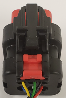
OpenIMU300RI Connector
OpenIMU Evaluation Kit Important Notice
This evaluation kit is intended for use for FURTHER ENGINEERING, DEVELOPMENT,
DEMONSTRATION, OR EVALUATION PURPOSES ONLY. It is not a finished product and may not (yet)
comply with some or any technical or legal requirements that are applicable to finished products,
including, without limitation, directives regarding electromagnetic compatibility, recycling (WEEE),
FCC, CE or UL (except as may be otherwise noted on the board/kit). Aceinna supplied this board/kit
"AS IS," without any warranties, with all faults, at the buyer's and further users' sole risk. The
user assumes all responsibility and liability for proper and safe handling of the goods. Further,
the user indemnifies Aceinna from all claims arising from the handling or use of the goods. Due to
the open construction of the product, it is the user's responsibility to take any and all appropriate
precautions with regard to electrostatic discharge and any other technical or legal concerns.
EXCEPT TO THE EXTENT OF THE INDEMNITY SET FORTH ABOVE, NEITHER USER NOR ACEINNA
SHALL BE LIABLE TO EACH OTHER FOR ANY INDIRECT, SPECIAL, INCIDENTAL, OR
CONSEQUENTIAL DAMAGES.
No license is granted under any patent right or other intellectual property right of Aceinna covering
or relating to any machine, process, or combination in which such Aceinna products or services might
be or are used.